Engineering 100-950
Powerboard Assembly Guide
While you could grab all components at once then get to soldering, it is best to grab the components ONE at a time, so that things don’t get lost or mixed up.
Procedure
-
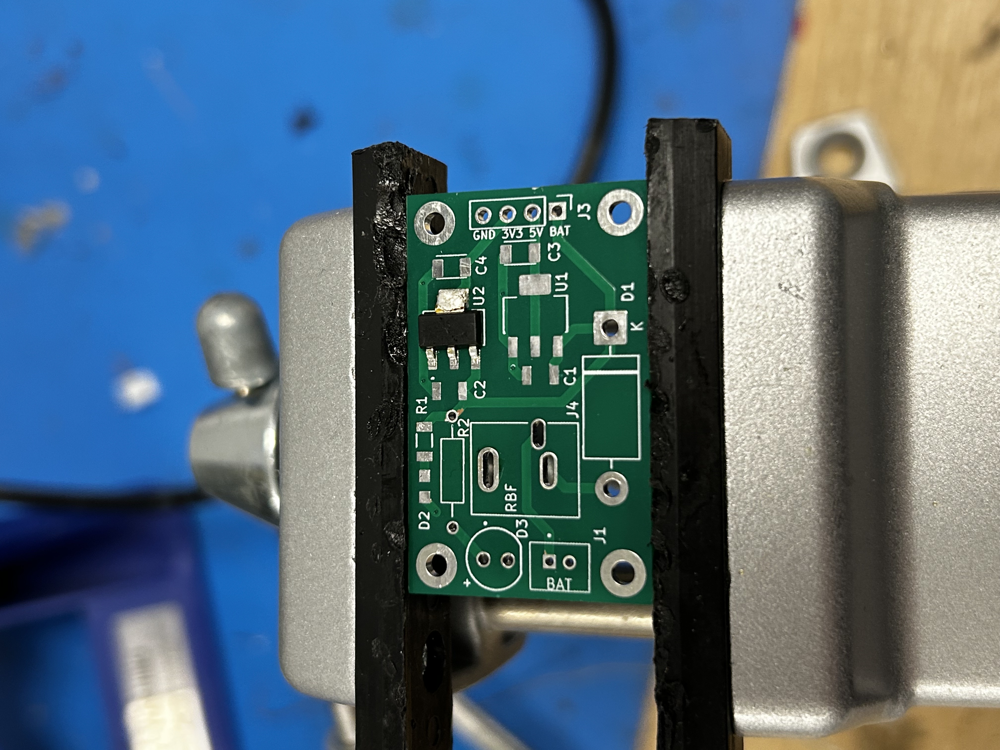
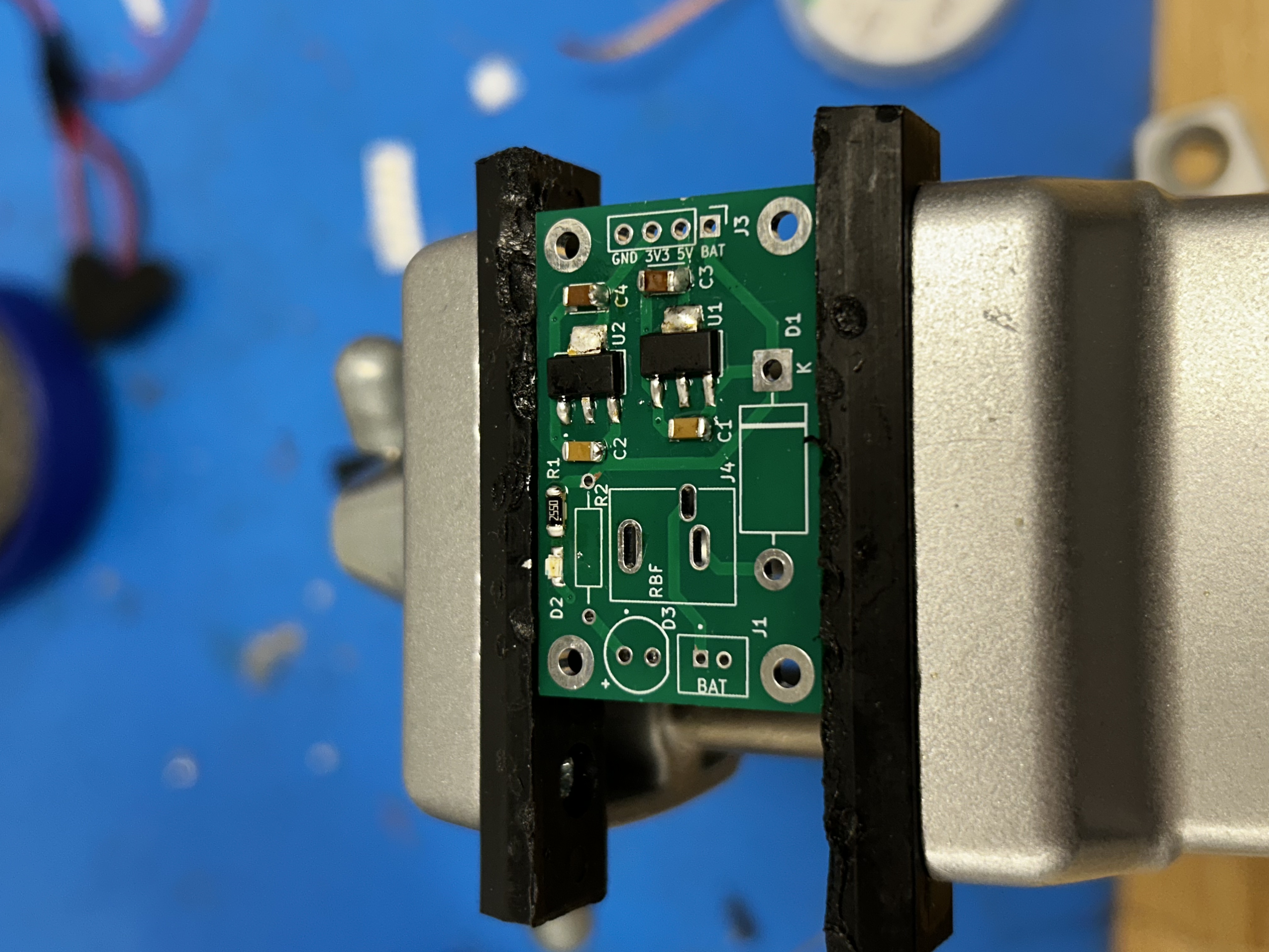
Take your PCB and solder on your 3v3 LDO.
Double and triple check that you 3v3 LDO is in the correct spot and is not in the 5v LDO spot. Have an instructor check after you finish this step.
-
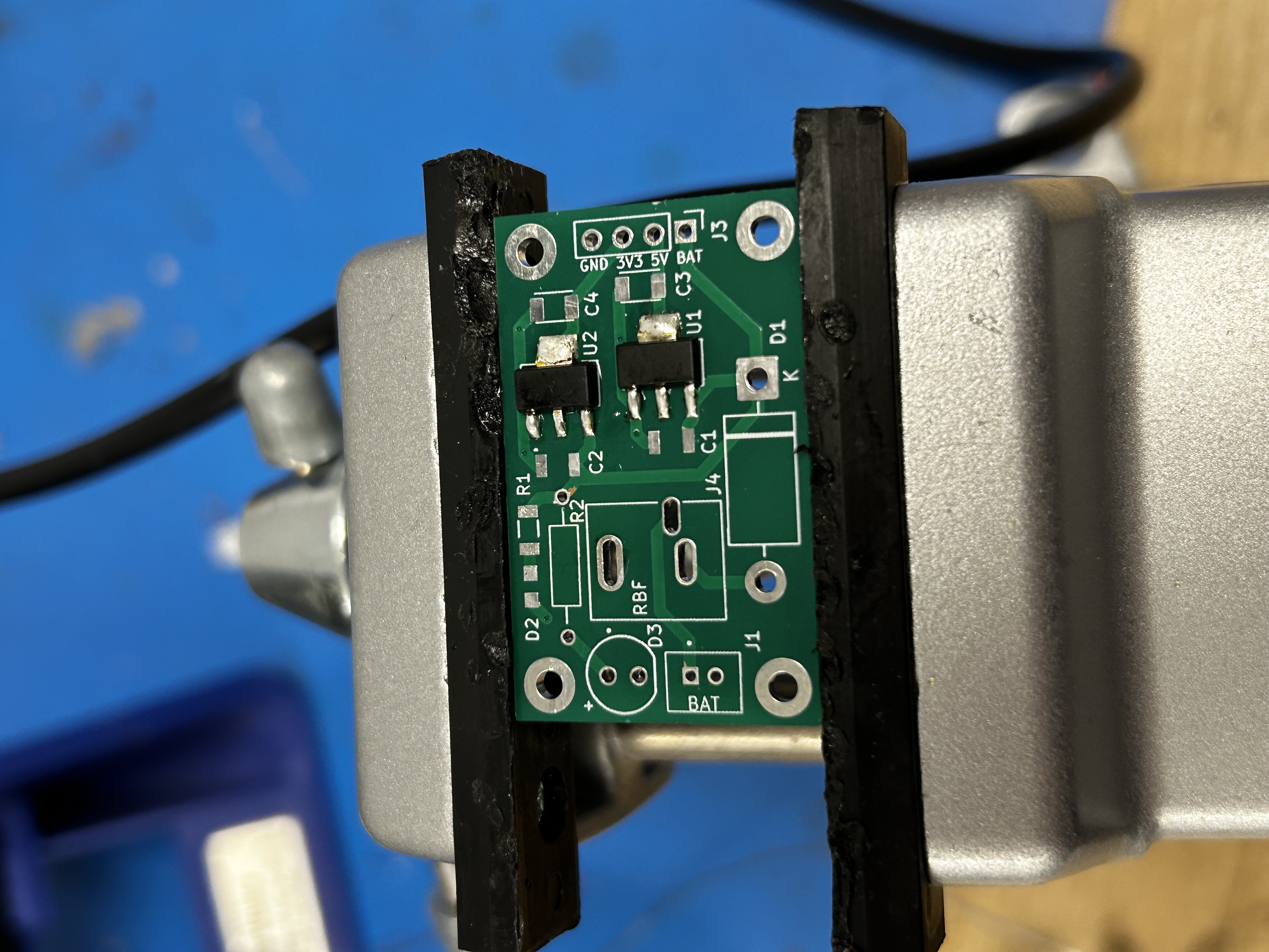
Next, solder on your 5v LDO.
-
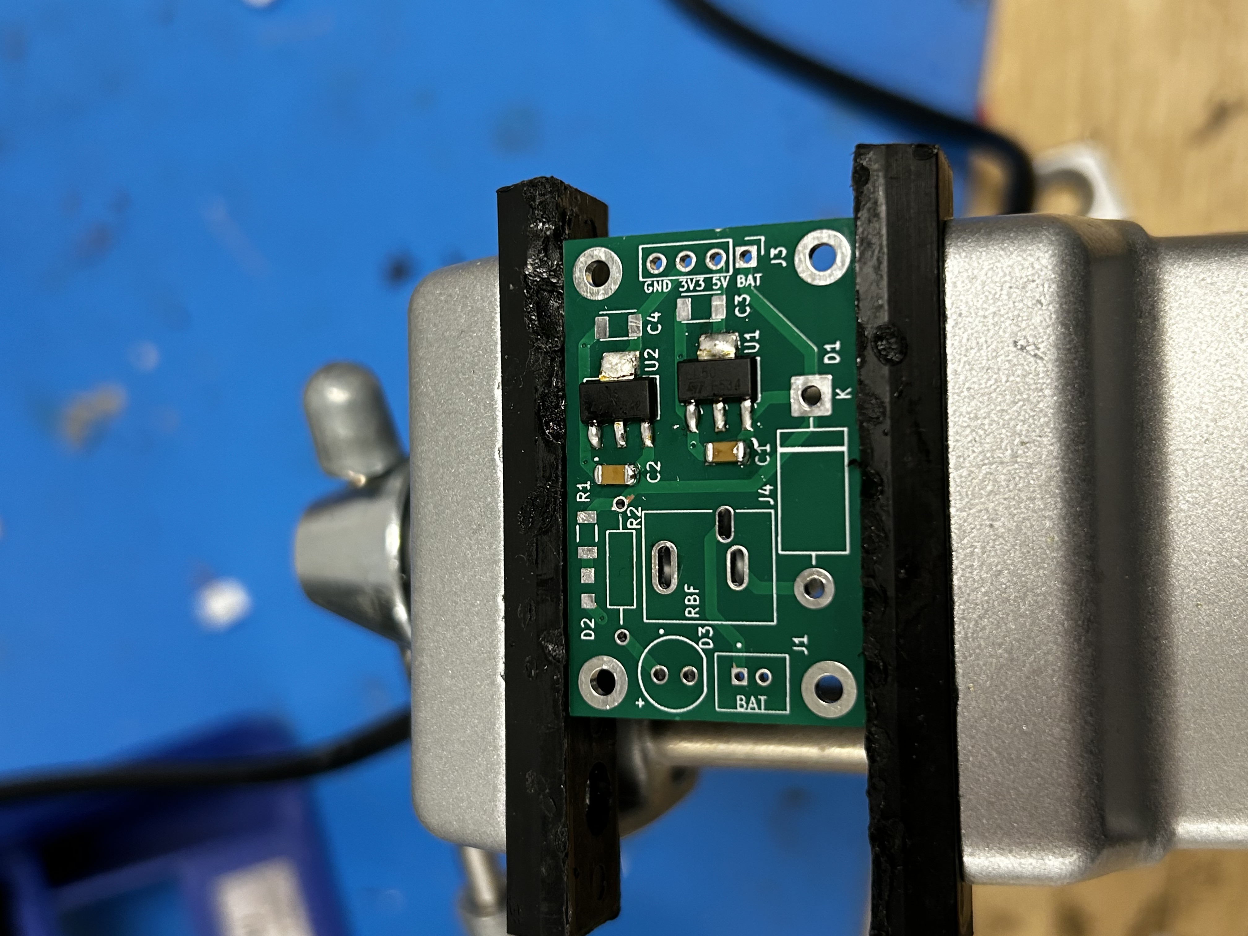
Now, solder the two 1uF capacitors. Note that they go on the left of the LDOs
-
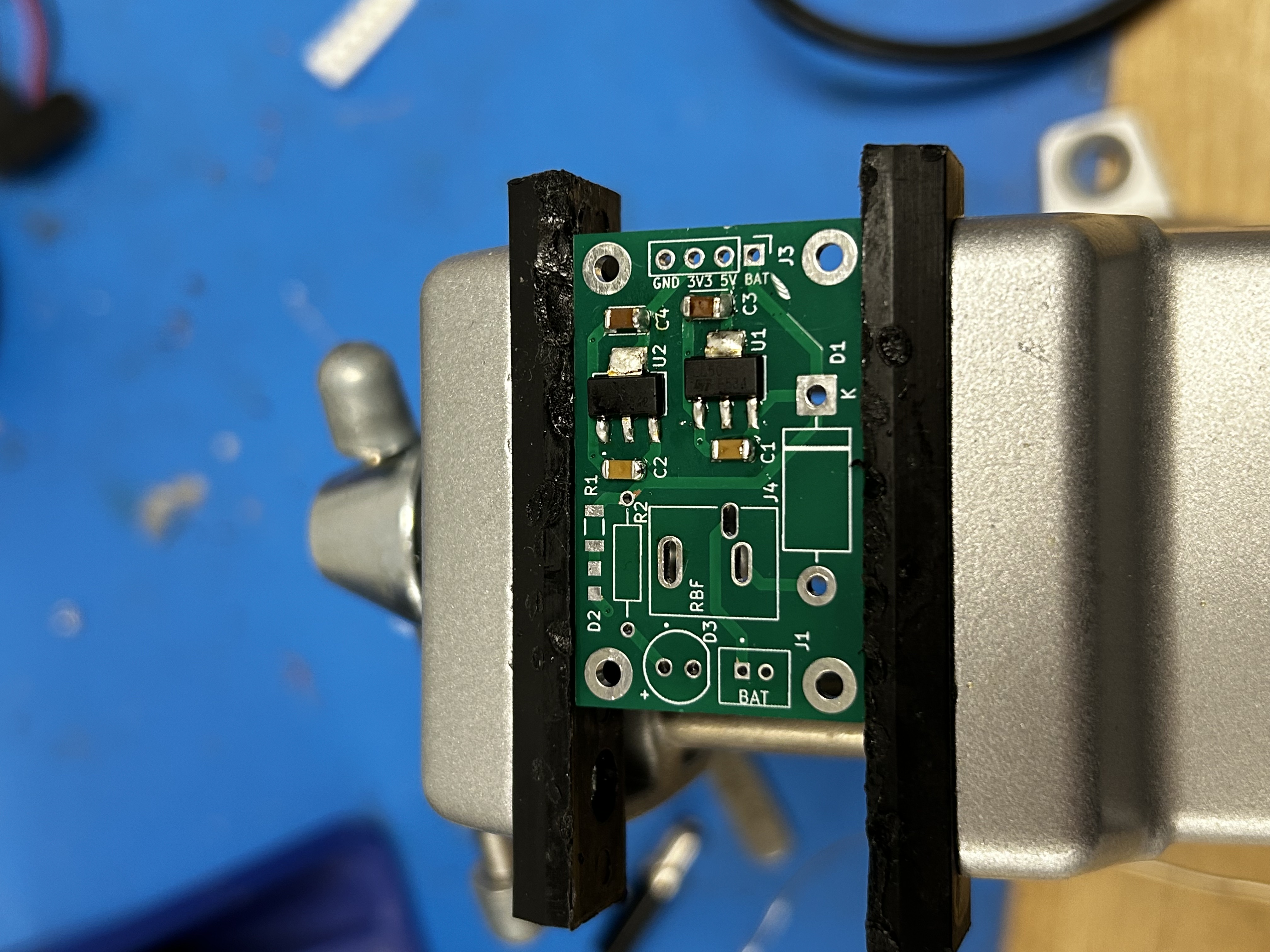
Solder the two 4.7uF capacitors on the other side of the LDOs:
Now, you can choose whether to add the surface mount LED or through hole LED. Since they both indicate battery power, there is no need to have both on the board. You can also choose to have the SMD installed on the board and then run wires from the through hole out to an LED visible from the outside of your payload (or if you have an external board that has a power LED).
-
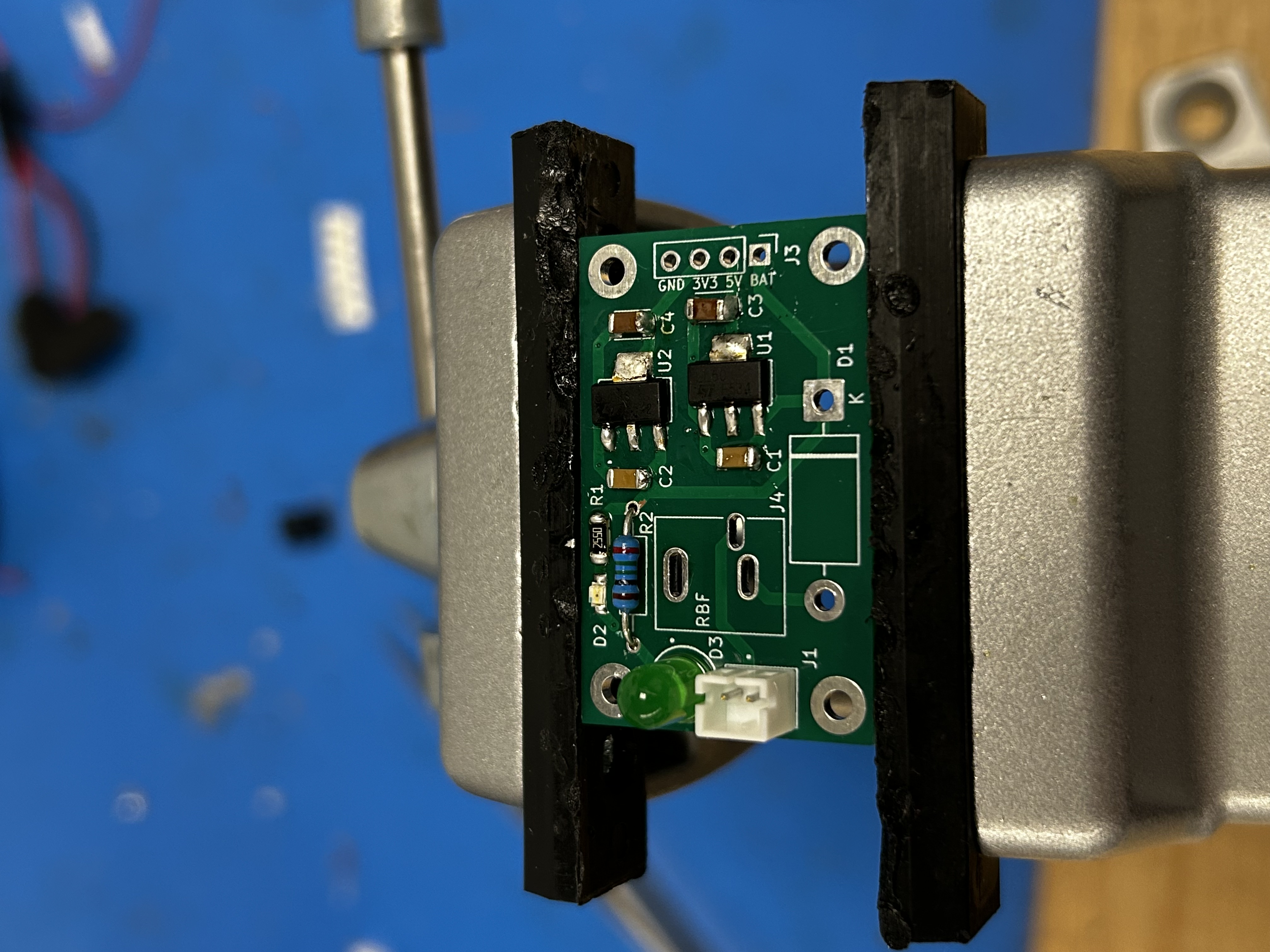
If you chose to install the surface mount LED, solder both the surface mount LED and resistor. Watch the polarity of the SMD LED
-
If you chose to install the through hole LED, solder both the through hole LED and resistor. Note that this photo has the power connector installed, ignore this until the step that asks you to install it.
-
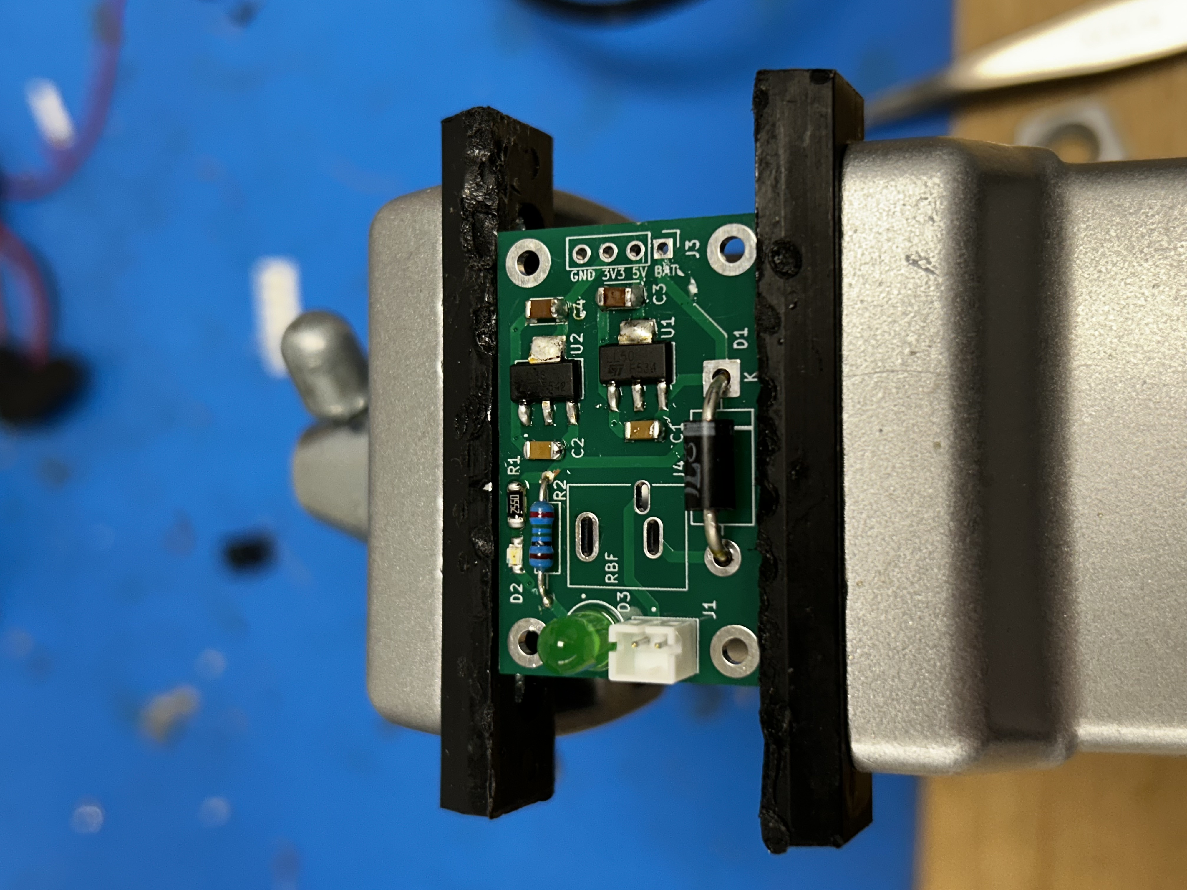
Next, solder the diode. Be careful bending the leads on the diode since they’re thick and potentially easy to break.
-
Solder the RBF jack:
-
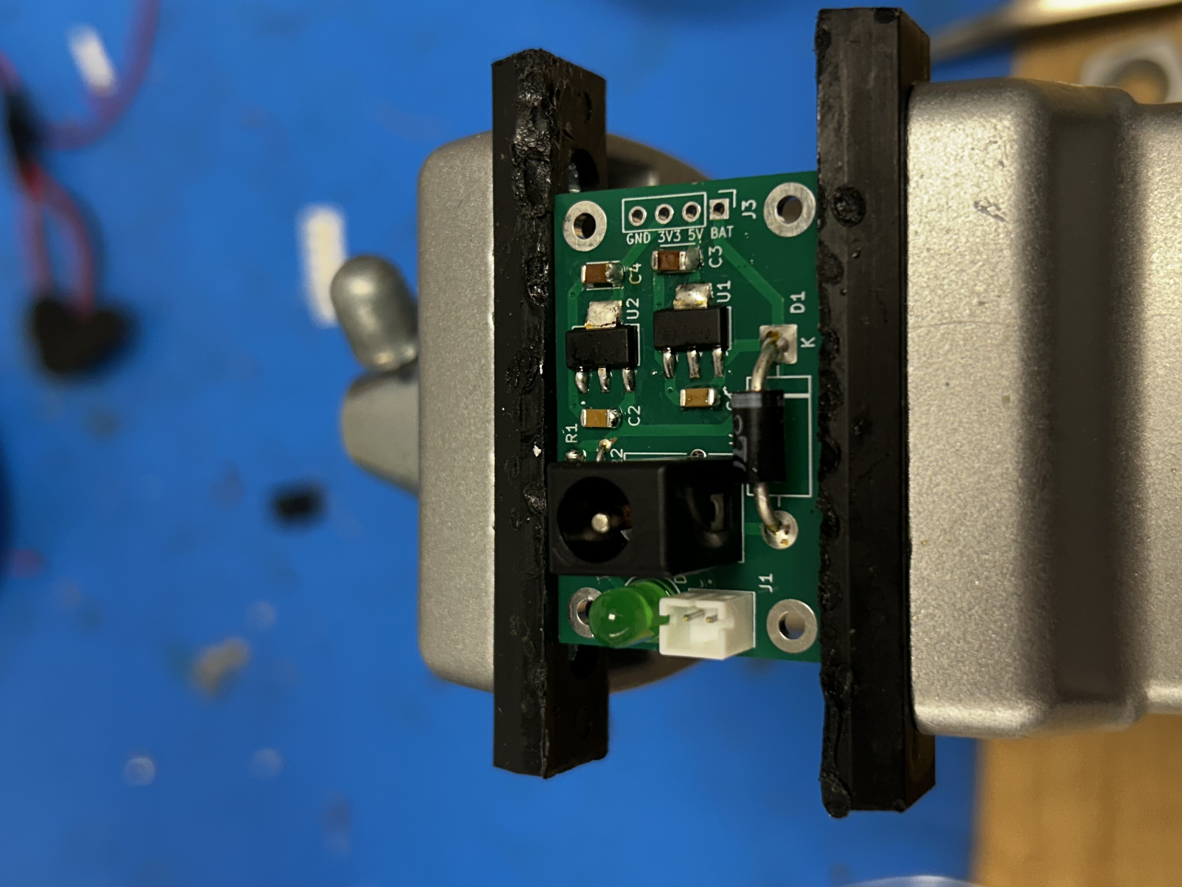
Finally, solder the power connector, insert your RBF plug, and you have a functioning power board!
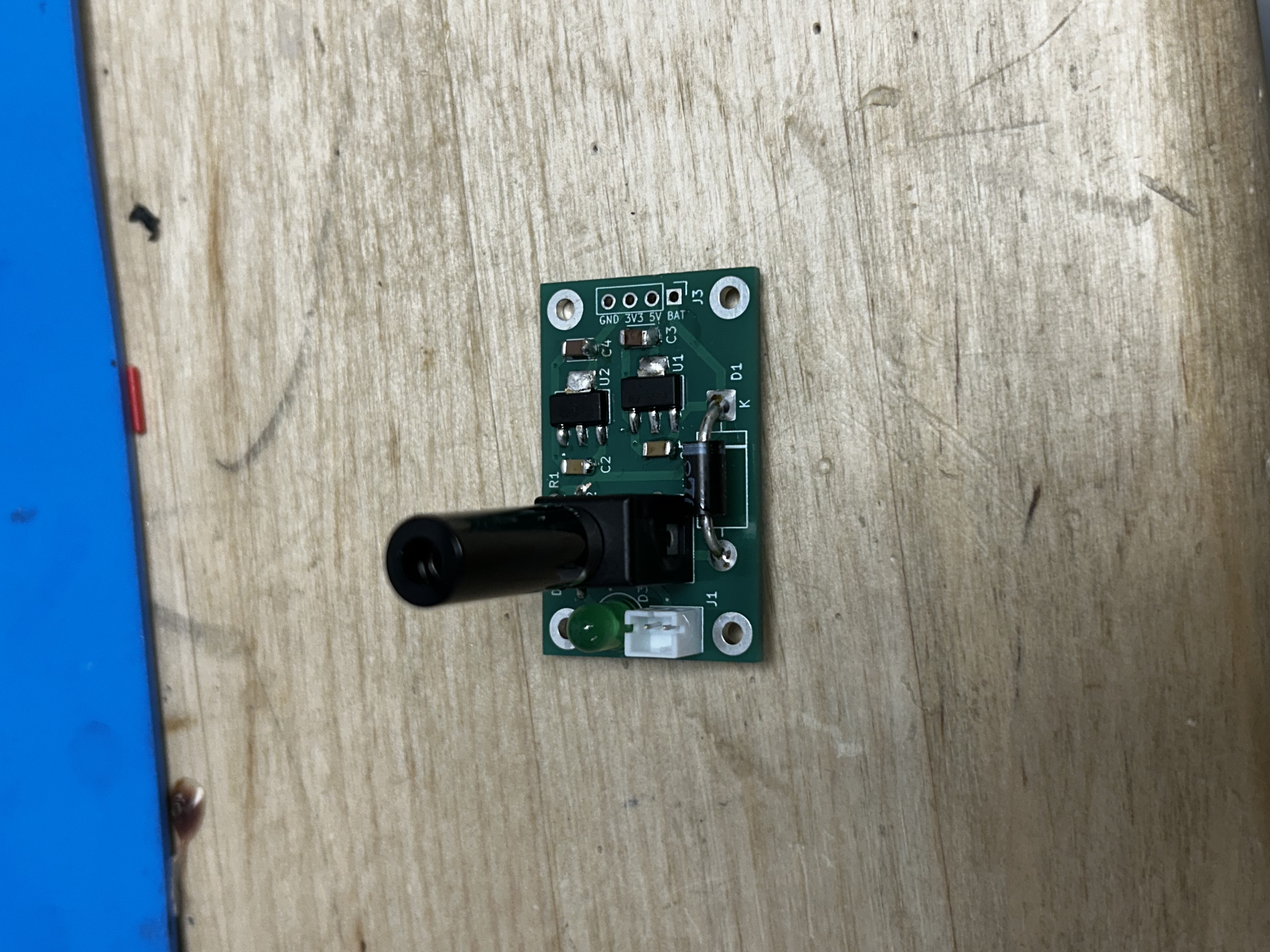
Have an instructor check your board and test it before moving on.
The final step before you can use your power board to supply your payload PCB is to solder the 4-pin header. How this is done will depend on how you designed your PCB to fit the power board, so it is recommended to wait until your main PCB is soldered to test fit and solder the pin header.