Engineering 100-950
Lab 4: Power Management
Contents
Materials
- 1 Arduino Nano
- 1 Breadboard
- 5.0V LDO
- 3.3V LDO
- 22 micro-Farad Capacitor
- Resistors for voltage divider circuit
- 9V Battery
- 1 Programming Cable (and adapters if necessary)
- A computer with the Arduino IDE installed and setup
- ENGR100-950 Arduino Library
- Completed sensor board from Lab 3
- ENGR 100 950 KiCAD libary
Safety
This lab involves working with a power supply which can provide higher voltages/currents than the Arduinos! Read the following sections carefully to maintain your safety and the safety of the components we are using.
It is very easy to accidentally short batteries when wires are connected to them. When not using the 9V battery, make sure that they have wire ends that are taped/secured, so the battery can not be shorted!
Electrostatic Discharge
In this lab we will start taking precautions when dealing with electronics as there is possibly of ESDs damaging components. When you eventually start soldering your PCB’s, you will be dealing with much smaller components and will thus absolutely need to take ESD precautions. For the subteam that will be working with the power portion of the lab: whoever is touching and interacting with the circuit will be needing to wear an ESD bracelet at all times.
An ESD bracelet provides your body contact through a conductive element to ground, therefore allowing any static discharge accumulated on your body to be discharged to ground. The blue ESD mats serve a similar purpose, and when using the smaller board to do the power lab please do so on the blue mat.
Introduction
Power management is one of the most critical aspects of any engineering system. Without the proper voltage levels, current levels, switching speeds, and noise suppression, most systems cannot work at their maximum efficiency.
Voltage regulators are an integral part of power management and allow a constant output voltage regardless of the input voltage (with constraints). This allows a steady voltage to components that need a small margin (error) in input voltage to output accurate data.
One type of voltage regulator is one we’ve discussed: the voltage divider. Previously, you have seen voltage dividers composed of two or more resistors in series. However, these configurations are not efficient, and so modern electronics do not usually include them. The most simple circuit for a modern voltage divider consists of a resistor and zener diode.
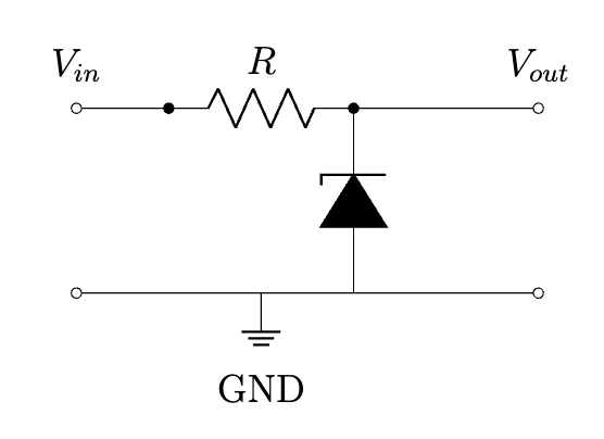
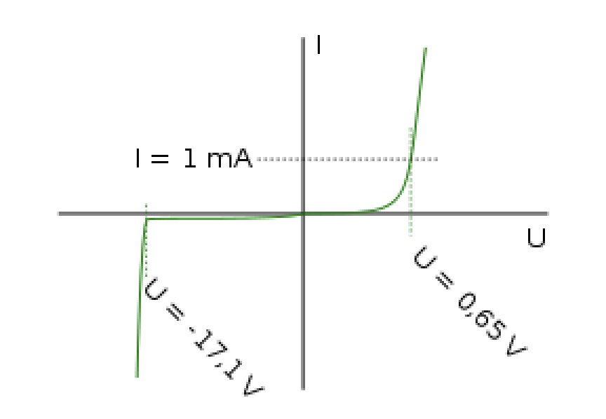
Zener diodes have a characteristic property wherein they allow current flow in the same direction as standard diodes (from anode to cathode) but they also allow current opposite direction once a “Zener Voltage” is reached. Once this voltage is reached, they operate reliably at the same voltage for increasing current levels. The I-V curve for a zener diode with a zener voltage of 17.1V is below. Notice how once the Zener Voltage is reached the voltage level is nearly constant for increasing current. The zener diodes used on voltage regulators have their zener voltages at the specified output voltage to ensure constant voltage at the output.
Procedure
This lab will involve building a circuit to test the behavior of two low-dropout (LDO) regulators, consolidating your sensors in to the first version of your final breadboard, and integrating the LDOs on to the breadboard to supply your Arduino with onboard power. To do this most efficiently, we recommend two to three team members work on the LDO testing circuit and the rest of the team members work on breadboard consolidation with the SD card and calibrating (completing lab 3). Your team will work together to integrate the LDOs to your sensor board (part 2). Members are welcome to work on what they’re most interested in, but no one team member should be assigned a task to work on alone. If you don’t have enough team members, consolidate teams and have two teams work together on both the boards.
Power Management
Make the circuit below on an (initially) empty breadboard. The power connection is coming from a 9V battery.
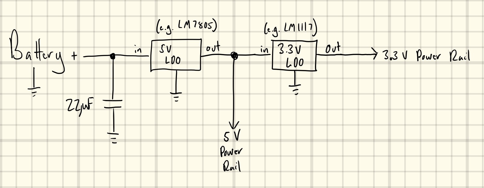
NOTE 1: We have a variety of through-hole LDOs. They may not match exactly what is specified in the diagram above. Google search for the LDOs that you have and verify their voltages and pin out configurations. It is up to you to get these right!
NOTE 2: The longer lead of the capacitor is the positive end. This means you should connect the longer lead to the side with a non-zero (non-ground) voltage, and the shorter lead to the ground line.
NOTE 3: Your system and your battery eventually need to share a common ground for you to get correct voltage measurements. Electrically connect all GND pins together to the battery’s negative terminal.
NOTE 4: We are now going to disconnect power whenever we rewire components on our breadboard!
Use a multimeter to measure the actual outputs of the 5V and 3.3V LDO lines. If the 5V line is not exactly 5V, it can cause errors on the conversions of the sensor data from voltage into actual ”geophysical” units (C, %, g, etc.) You may want to use the reading from the 5V LDO in your calibration calculations.
Have a staff member check your circuit before you proceed.
A staff member will work with you on replacing the battery with a power supply.
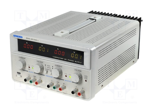
Power Supply
The figure below shows a lab power supply. This is a device we frequently use in labs to power circuits: sometimes to avoid using the USB cable and a computer for power, and sometimes when we need a higher voltage than can be provided by the Arduino. There are multiple channels on the power supply, to allow for powering more than one device or produce more than one voltage at the same time.
You will be using the power supply on your workbenches today to power portions on your circuit. Please do NOT connect the power supply to the board until looked at by one of the instructors. The power supply has been current-limited at 500 mA and can cause some serious damage if used improperly. Please call the instructor to have them examine the breadboard before connecting to power. Also, do not increase the power supply voltage above 10V.
The wires to the power supply should already be connected (Red = positive and Black = negative). Connect the red wire to the positive rail located at the top of the breadboard, and the black wire to the blue rail located adjacent to it. Do not connect them in holes adjacent to one another; we want to remove any possibility of the two wires accidentally coming in contact and shorting the circuit. Please do not turn on the power supply until your connections have been verified by an instructor. Please do not adjust the wires connected to the power supply unless the supply is turned off. You can use this rail to power the components of your circuit as illustrated in Part 1 below.
Do not turn on the power supply until your connections have been verified by an instructor!
Slowly reduce the voltage on the power supply (you can use the “Coarse” knob but rotate it slowly). Reduce it to 0V in increments of 1V, using a multimeter to record the voltage on the 5V and the 3.3V lines. Note the power supply voltage at which the 5V line no longer reads 5V and the voltage at which the 3.3V line no longer reads 3.3V. There will be some variation, so let’s assume that once it is more than .15V away from the value it has sufficiently dropped.
Turn the power supply off!
Battery Power
Disconnect the power supply, and add an Arduino to your power board. Make two voltage divider circuits, one hooked up to the Vin pin of the 5V LDO (i.e., this one will measure (half) the battery voltage) and one hooked up to the Vout pin of the 5V LDO (i.e., this should measure (half) 5V). Attach the output pin of the 3.3V LDO to an analog pin on the Arduino also. You should now be able to make a program that will measure the battery voltage, the 5V line voltage, and the 3.3V line voltage.
Remember to use color coding for your power lines and data lines. This will dramatically assist you in the debugging of your system if things don’t work.
Note that the output lines of the 5V and 3.3V lines are now your main power rails. The 5V LDO output line should be connected directly to the 5V line on the Arduino and there should be NO connections to the Vin pin on the Arduino. The 3.3V line does NOT get connected to the 3.3V line on the Arduino!
Once you have verified that everything is hooked up as it should be, add a 9V, battery to the top rail of your bread-board to power your LDO circuit and power on your Arduino. When you connect your battery, everything should turn on and start reporting data (although you can’t see it, since your computer is not hooked up yet). Hook up the USB to the Arduino and measure the battery voltage, 5V line voltage, and 3.3V line voltage using a program. Take a screenshot that shows that you are measuring the proper voltages on the different lines!
Take some pictures of this beautiful power board!
Consolidation
NOTE: We are now going to disconnect power whenever we rewire components on our breadboard!
Once you have all of your sensors working and saving data to the SD card on one breadboard, and your power system working on another breadboard, consolidate the breadboards. You should then have battery supplied 5V and 3.3V rails (with grounds), a single Arduino, an SD Card writer, and a bunch of sensors. Make sure all of your grounds are grounded to Arduino Ground. You can have all of these systems across multiple breadboards. For simplicity sake, we recommend 2 or less breadboards.
Take some pictures of your (nearly) complete system board!
Verify that your board runs and records data properly (including the battery voltage, 5v line, and all of your sensor data).
Put your completed board into the cold chamber for at least 5 minutes, recording data the entire time. Make plots of the data using Matlab or some other software.
Submission
On Canvas, you will submit ONE PDF that will include all of the following:
- A short description of your power supply tests with the cutoff voltages that you found.
- A picture of your completed power board.
- A picture of your completed consolidated board.
- A picture of your battery with the ends of wires safely taped and secured so that they can not short.
- A (complete) system-level block diagram of your completed system. The color coding on your system-level block diagram should match the color coding on your board. You should be able to look at your picture of your board and your system-level block diagram and understand what is going on with your board. Not every line needs to be drawn though (like ground lines should NOT be on the block diagram).
- A (complete) schematic of your completed system (IN KICAD). Make sure to update your Arduino symbol to the new one in the libaries (We uploaded a new and improved Arduino Nano Every Symbol. You should be using this one instead of the default KiCAD one from now on).
- A screenshot of your (battery, 5V, and 3.3V) voltage readings from your Arduino (serial monitor) on your power board.
- Nice plots that show data from your completed board going into the cold chamber for at least 5 minutes. The data should be calibrated with plots in actual geophysical units, including time (in minutes). For simplicity, any CSV files should print voltages, and MATLAB should perform the conversions to geophysical units.
- Discuss whether the battery voltages changed as it got colder. Is there any relationship between temperature and battery voltage?
To put said content into a PDF, it is suggested you create a new Google Doc (docs.new) and paste your images and write any text in the document. Export/Download this document as a PDF and upload it. DO NOT SUBMIT A GOOGLE DOC FILE OR SPREADSHEET FILES.
Submitting anything other than a single PDF may result in your work not being graded or your scores being heavily delayed.